
Raspberry Pi Motor Control with Relay
Controlling external electrical devices such as DC motors through a microcontroller like the Raspberry Pi requires safe interfacing methods. One such approach involves the use of a relay switch—an electrically operated switch that isolates and manages high-power components using low-power signals from the Raspberry Pi. This experiment focuses on demonstrating how to use a relay module to control a DC motor from the Raspberry Pi's GPIO pins.
Components and Their Functions
1. Raspberry Pi
Acts as the main controller in this experiment.
Sends GPIO signals to the relay module based on the control logic.
Operates at 3.3V logic level, which is compatible with most relay modules.
Cannot directly drive high-current devices like motors, so it relies on the relay for switching.
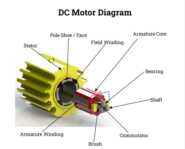
#### 2. DC Motor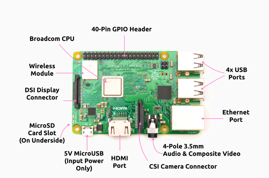
A rotary electrical machine that converts electrical energy into mechanical rotation.
Operates on the principle that a current-carrying conductor in a magnetic field experiences a force, producing motion.
Used here as the output device, powered by an external source and activated through the relay.
Working: When current flows through the motor’s windings, it creates a magnetic field that interacts with the permanent magnets (or field windings), producing a torque that rotates the motor shaft. The speed and direction can be controlled by varying the voltage and polarity.
Common in robotics, automation, and electronics for its simplicity and ease of control.
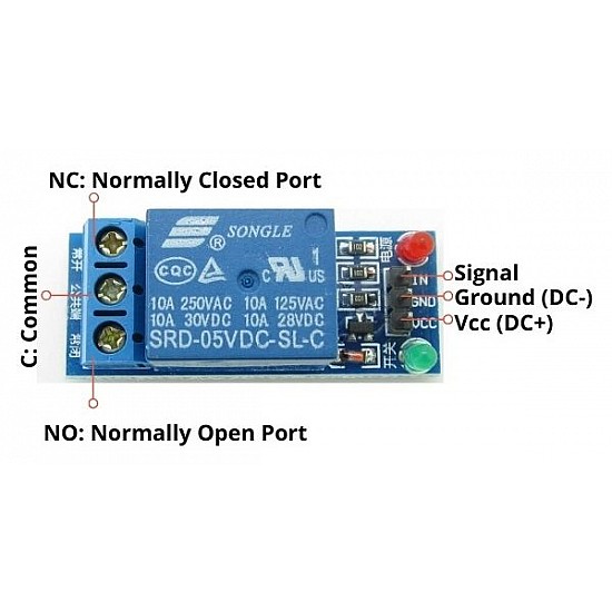
3. Relay Module (5V)
- An electromechanical switch that uses a small electrical signal to control a higher-powered circuit.
- It uses a GPIO pin on the Raspberry Pi to activate its internal switch.
- Provides electrical isolation and safely controls the motor’s higher voltage, protecting the Raspberry Pi.
- Working: When the Raspberry Pi outputs a HIGH signal to the relay’s control pin, it energizes an internal coil, creating a magnetic field. This pulls a metal contact to close (or open) the circuit connected to the motor, allowing or cutting off current flow.
- This module allows control over the DC motor's power supply using logic signals.
4. 9V Battery
Provides an external power source for the DC motor, preventing the Raspberry Pi from bearing the current load.
Powers the motor when the relay closes the circuit.

Explanation of Each Connection
1. Connect the Relay to the Raspberry Pi
- Connect the 3.3V pin (Physical Pin 1) of the Raspberry Pi to the VCC pin of the relay to supply power.
- Connect a GND pin (e.g., Physical Pin 9) of the Raspberry Pi to the GND pin of the relay to complete the control circuit.
- Connect GPIO21 (Physical Pin 40) of the Raspberry Pi to the Input pin of the relay to control its switching mechanism.
2. Connect the Relay to the Motor and Battery
- Connect the COM (Common) pin of the relay to the positive (+) terminal of the 9V battery.
- Connect the NO (Normally Open) pin of the relay to the positive (+) terminal of the DC motor.
- Connect the negative (-) terminal of the 9V battery to the negative (-) terminal of the DC motor to complete the motor circuit.
3. Verify Connections
- Double-check all physical connections to ensure accuracy, polarity, and proper wire placement.
- Ensure the breadboard layout matches the circuit diagram.
4. Software Execution
- After completing all the wiring, click the “Code” button followed by the “Submit” button in the software interface (if applicable).
- This will trigger the GPIO logic to activate the relay and control the motor.
5. Final Verification
- Confirm that the motor operates as expected when the GPIO output toggles.
- Recheck the circuit against the schematic to verify correctness.