
Raspberry Pi LED Blink Program
Hardware Setup
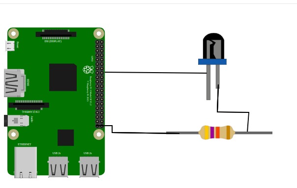
Identify the two pins of the LED:
- The longer pin is the positive terminal (anode).
- The shorter pin is the negative terminal (cathode).
Connect the negative terminal (shorter pin) to the GND pin of the Raspberry Pi.
Connect the positive terminal (longer pin) to a separate line on the breadboard.
Attach one end of a resistor to the same line as the positive LED terminal.
Connect the other end of the resistor to a GPIO pin on the Raspberry Pi (e.g., GPIO17).
Software Setup
1. Controlling the LED with Python 3 on Raspberry Pi OS
Once the hardware is set up, the LED can be controlled using Python 3. The following process enables LED control:
- Import the
RPi.GPIOmodule for GPIO access. - Import the
timemodule for delays. - Define a global constant for the LED’s GPIO pin number.
- Configure the Raspberry Pi to use BCM numbering (GPIO numbers).
- Set up the GPIO pin as an output using
GPIO.setup().
2. Making the LED Blink
- Maintain the same GPIO configuration.
- Implement an infinite loop that toggles the LED on and off at set intervals.
- The LED remains ON for 1 second and OFF for 2 seconds.
- The loop runs indefinitely until manually stopped using the stop button in the Thonny IDE or
CTRL+Cin the terminal.
Booting the Raspberry Pi OS
Before setting up the LED, ensure your Raspberry Pi is ready with a working operating system.
Prepare the microSD Card
- Download the Raspberry Pi Imager on your computer.
- Insert a microSD card (8 GB or larger).
- In Raspberry Pi Imager, select the desired OS (e.g., Raspberry Pi OS 32-bit), choose your microSD card, and click Write.
Insert the microSD Card
- Safely eject it from your computer and insert it into the Raspberry Pi’s microSD slot.
Connect Peripherals
- Attach a monitor via HDMI.
- Connect a USB keyboard and mouse.
- Optionally, connect Ethernet (Wi-Fi can be set up later).
Power On
- Connect the Raspberry Pi to its power supply.
- The system will boot into Raspberry Pi OS setup automatically.
First-Time Setup
- Follow the on-screen prompts to set your language, keyboard layout, Wi-Fi, and software updates.
Once the OS is up and running, proceed to the hardware setup.
Python Code Implementation
import RPi.GPIO as GPIO
          import time

          # Define the GPIO pin number for the LED
          LED_PIN = 17

          # Set the GPIO mode to BCM (Broadcom pin-numbering scheme)
          GPIO.setmode(GPIO.BCM)

          # Set up the LED pin as an output
          GPIO.setup(LED_PIN, GPIO.OUT)

          try:
              while True:
                  # Turn the LED on (HIGH state)
                  GPIO.output(LED_PIN, GPIO.HIGH)
                  time.sleep(1)  # Wait for 1 second

                  # Turn the LED off (LOW state)
                  GPIO.output(LED_PIN, GPIO.LOW)
                  time.sleep(2)  # Wait for 2 seconds

          except KeyboardInterrupt:
              # Clean up GPIO settings when exiting the program
              GPIO.cleanup()